Projects uses my WS2812B LEDs driver library for controlling whole tape/strip of addressable LEDs. Certain protocol is achieved by controlling PWM via DMA mode. List of values prepared for every single diode is transfered as PWM signal of exact period time. It is expected that user knows how to configure new project and etc. in STM32CubeIDE.
Used:
- STM32G030C8 microcontroller
- WS2812B addressable LEDs tape
- STM32CubeIDE (dedicated IDE for ST microcontrollers)
WS2812B driver libs are written in C and are separated from STM32 HAL or other hardware dependent parts of project. Library consists of:
- ws2812b_driver.c
- ws2812b_driver.h
They can be found here: https://github.com/FRSH-0109/WS2812B_LED_Strip_Driver.git
It describes what should be changed in the driver header file.
Driver .c and .h files have to be copied/imported to your project Src( .c) and Inc( .h) folders.
https://github.com/FRSH-0109/WS2812B_LED_Strip_Driver.git
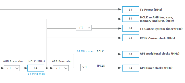
Set MCU clock and timers clock frequnecy
In my project the frequency of mcu is set to 64MHz, as well as clock source for Timers(APB timer clocks)
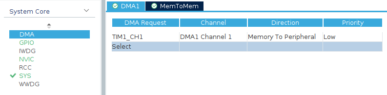
Created function have to send proper PWM values, it is recommended to use DMA mode(memory to peripheral).
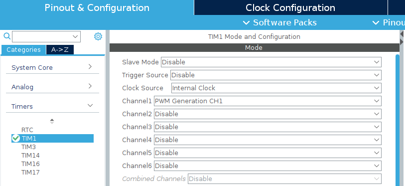
Selecting Timer, choosing clock source and channel mode(PWM generation).
Channel number is strongly connected with signal output pin.
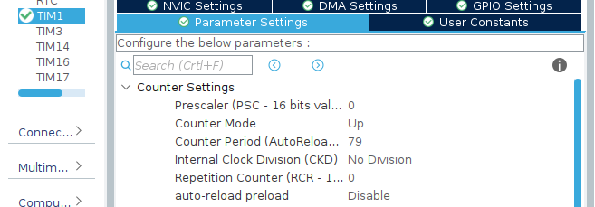
Set proper PWM parameters
Prescalers is simply the divisor(divisor = value + 1, so written 0 sets prescaller to 1) between Timer APB clocks frequency and used in our Timer1 frequency. 64MHz / 1 = 64MHz on Timer1 clock.
Counter Period is the value on which our counter will reload(start counting again from 0). It is set to 79(0-79 gives 80 counter steps). So our one timer cycle would count to 80 times on 64MHz freq, 64Mhz / 80 = 800000Hz = 800kHz = (1/800Khz)s = 0,00125ms = 1,25us(exactly what we would like to achieve with our specific diodes type).
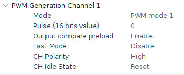
Make sure that your Timer channel polarity is set to high, every signal have to start by high volatge level.
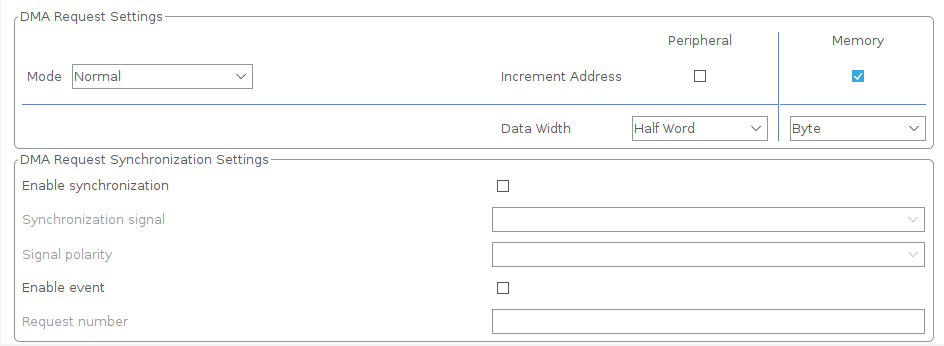
Enable DMA mode for Timer
DMA have to be configured into memory to peripheral mode(array of values into PWM signal process).
Timer data width: Half Word(16bit), beacuse we are using 16bit Timer1
Memory data width: Byte(8bit), becuase array containing pwm data is uint8_t type variable
Incerement adderess: memory only
To make whole driver library more hardware independent, send function have to be created by user.
Only thing to do is to get the PWM data array and pass it to the DMA PWM pulse creating function.
In case using the STM32 HAL, it will look like this:
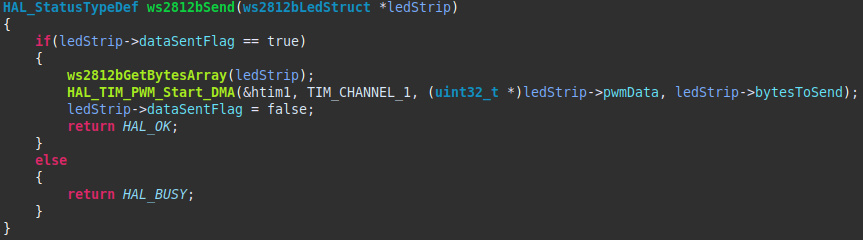
ws2812bGetBytesArray(ledStrip); - translates RGB data stored in ledStrip structure into pwm data, also stored in structure. This process is separeted into function, to let user make one translation after changing colors of many diodes.
HAL_TIM_PWM_Start_DMA(&htim1, TIM_CHANNEL_1, (uint32_t *)ledStrip->pwmData, ledStrip->bytesToSend); - STM32 HAL function, which sends PWM via DMA. It needs few arguments like:
(uint32_t *)ledStrip->pwmData- pointer to begining of PWM data arrayledStrip->bytesToSend- how many bytes have to be send
ledStrip->dataSentFlag; - this boolean variable prevents from sending data before previous one haven't been finished
Timer pulse finished interrupt
It is necessary to handle function which controls when data array has been send completely. I used HAL interrupt routine which is marked as __weak in default HAL files. After the last byte of data has been represented as PWM signal, interrupt changes dataSentFlag, so next send function can be executed successfully. Also the Timer PWM DMA sending routine is stopped, because normally it would work continiously.

Setting red color on every two diodes. Delay can be removed

Creating wave effect on led tape(changable width). Every call of wave function generates next frame of it.
