

A PID-based control integration for Home Assistant that regulates a numeric output entity based on a measured process value and a setpoint, with optional grid import/export limiting.
Designed for energy flow control scenarios such as inverter power limiting, load control, EV charging, or grid balancing.
Solar Energy Controller is an open-source PID control integration for Home Assistant, designed to provide flexible energy flow control for solar and grid-connected systems. This integration enables precise control of energy systems through a normalized, percent-based PID algorithm that works across different sensor types and units.
The integration is developed and maintained as an open-source project. For more information, visit the GitHub repository.
This integration is generic and does not talk directly to a specific hardware brand or model. It works with any devices that expose the required Home Assistant entities.
The following types of setups are known to work well with Solar Energy Controller, as long as they expose compatible entities:
- Solar inverters with a numeric power limit entity (e.g.,
number.inverter_max_power) and power sensor (e.g.,sensor.solar_power) - EV chargers with a numeric current or power limit entity (e.g.,
number.ev_charger_limit) and power/current sensors - Battery systems where charge/discharge power can be controlled via a
number/input_numberentity - Smart relays or load controllers that expose a numeric control for power/current/percentage
- Any energy or load control scenario where:
- The process value (PV) is available as a
sensor,number, orinput_number - The setpoint (SP) is available as a
numberorinput_number - The output (actuator) is a
numberorinput_numberentity
- The process value (PV) is available as a
Note: The integration does not depend on a specific inverter/charger brand. As long as the device is already integrated into Home Assistant and exposes compatible entities, it can be used.
The following setups are not supported or not recommended:
- Devices that do not expose a numeric control entity (e.g., only
switchorbinary_sensorwithout anumber/input_numberoutput) - On/off-only devices where control is purely binary (no numeric output to regulate)
- High-speed real-time control systems that require sub-second response (e.g., motor drives, fast robotics)
- Devices that are not integrated into Home Assistant or do not provide entities for PV/SP/Output
If you are unsure whether your device is supported, check if you can:
- Read the measurement you want to control (PV) as a
sensor,number, orinput_number - Write a numeric value to a
numberorinput_numberentity that affects the device (Output) - Optionally read grid power as a
sensor,number, orinput_numberfor the grid limiter
- PID controller (Kp / Ki / Kd)
- Internal 0–100% normalized control
- Percent-based PID tuning (unit- and device-independent)
- Anti-windup with tracking
- Derivative on measurement
- Multiple runtime modes:
- Automatic setpoint
- Manual setpoint
- Manual output
- Hold
- Optional grid import/export limiter
- Optional output rate limiting
- Fully configurable from the Home Assistant UI
The controller internally normalizes PV, SP, and Grid Power to a 0–100% range using configured raw min/max values:
- PV (Process Value) → 0–100%
- SP (Setpoint) → 0–100%
- GRID (Grid Power) → 0–100% (used only when limiter is enabled)
- PID OUT → 0–100%
The PID algorithm always operates in percent, while:
- Sensors continue to display raw, real-world values
- The output entity receives scaled real-world values (based on your output min/max)
This makes the controller:
- stable across different sensors and units (W, A, V, %, etc.)
- predictable to tune
- resilient when changing devices (only ranges change)
Kp, Ki, and Kd are tuned in percent space.
What this means:
- 100% PID output represents your configured maximum output
- PV/SP/Grid units do not matter (because values are normalized before PID)
- Gains do not need re-scaling when you change sensor ranges or units
- Home Assistant 2023.9.0 or later
- HACS (Home Assistant Community Store) installed and configured
If you don't have HACS installed yet:
- Follow the HACS installation guide
- Restart Home Assistant
- Complete the HACS setup wizard
- In HACS, go to Integrations → ⋮ → Custom repositories
- Add this repository URL:
https://github.com/isystemsautomation/ha-solar-energy-controllerand select Integration as the category - Click Add and wait for the repository to be added
- Search for Solar Energy Controller in HACS
- Click Download to install the integration
- Restart Home Assistant
- Go to Settings → Devices & Services → Add Integration
- Search for Solar Energy Controller and follow the setup wizard
To remove the Solar Energy Controller integration:
- Go to Settings → Devices & Services
- Find Solar Energy Controller in the list of integrations
- Click on the integration entry
- Click the ⋮ (three dots) menu in the top right corner
- Select Delete and confirm the removal
- (Optional) To remove the integration files from HACS:
- Go to HACS → Integrations
- Find Solar Energy Controller
- Click ⋮ → Remove
- Restart Home Assistant to complete the removal
Note: Removing the integration will delete all configuration entries and entities. Any automations or scripts that reference these entities will need to be updated.
During setup you select the entities used by the controller and define their operating ranges for normalization.
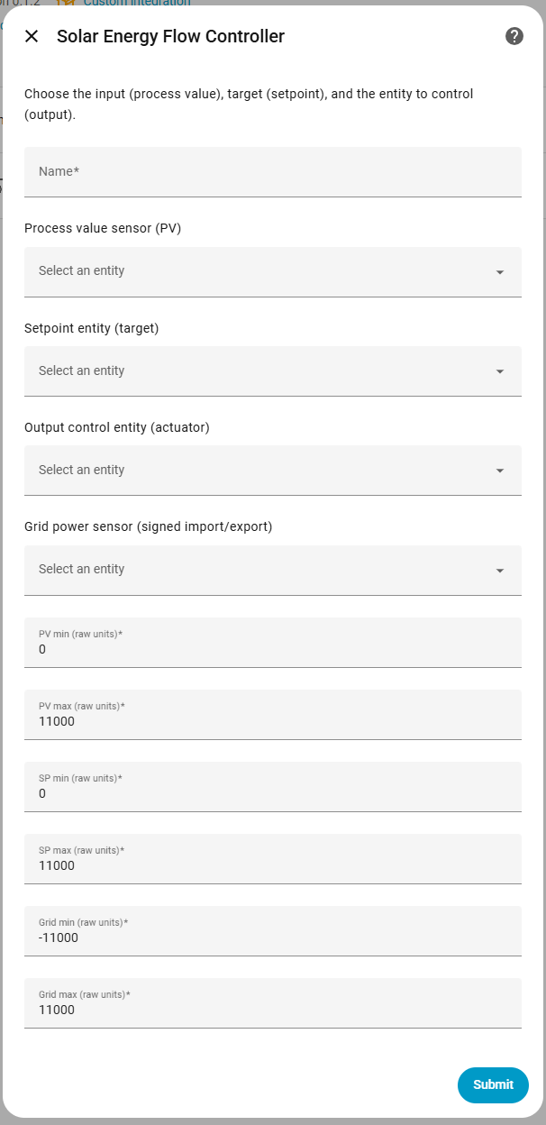
The following parameters are required during the initial setup:
Name:
- Description: A friendly name for this controller instance (e.g., "Solar Inverter Controller", "EV Charger PID").
- Where to find: Choose any descriptive name that helps you identify this controller in Home Assistant.
Process Value Entity (PV):
- Description: The entity that provides the measured process value that the PID controller will regulate. This is the "sensor" that tells you the current state.
- Where to find: Go to Settings → Devices & Services → Entities and search for your sensor. Examples:
sensor.solar_power,sensor.grid_voltage,number.current_setpoint. - Supported domains:
sensor,number,input_number - Example: If controlling solar inverter power, this would be your power sensor (e.g.,
sensor.solar_inverter_power).
Setpoint Entity (SP):
- Description: The entity that provides the target setpoint value. The PID controller will try to keep the process value equal to this setpoint.
- Where to find: Go to Settings → Devices & Services → Entities and search for your setpoint entity. This is typically a
numberorinput_numberentity that you can set manually or via automation. - Supported domains:
number,input_number - Example: If you want to maintain 5000W, create an
input_numberentity (e.g.,input_number.target_power) and set it to 5000.
Output Entity:
- Description: The entity that the PID controller will write to. This is the "actuator" that controls your system (e.g., inverter power limit, charger current).
- Where to find: Go to Settings → Devices & Services → Entities and search for your output entity. This must be a
numberorinput_numberentity that accepts numeric values. - Supported domains:
number,input_number - Example: If controlling an inverter, this would be the power limit entity (e.g.,
number.inverter_max_power).
Grid Power Entity:
- Description: The entity that provides grid power measurement (signed import/export). Required if you plan to use the grid limiter feature.
- Where to find: Go to Settings → Devices & Services → Entities and search for your grid power sensor. This should be a sensor that reports positive values when importing from grid and negative when exporting.
- Supported domains:
sensor,number,input_number - Example:
sensor.grid_powerwhere positive = importing, negative = exporting.
PV min / max:
- Description: The minimum and maximum expected values for the process value in raw units. These define the range used to normalize the PV to 0–100% internally.
- Where to find: Check your process value sensor's typical operating range. For example, if your power sensor reads 0–10000W, set min=0, max=10000.
- Default: -5000.0 to 5000.0
- Example: If your PV sensor measures power in watts and ranges from 0W to 10000W, set PV min=0, PV max=10000.
SP min / max:
- Description: The minimum and maximum expected values for the setpoint in raw units. These define the range used to normalize the SP to 0–100% internally.
- Where to find: Check what range your setpoint entity accepts. This should match the range you want to control.
- Default: -5000.0 to 5000.0
- Example: If your setpoint can be set from 0W to 10000W, set SP min=0, SP max=10000.
Grid min / max:
- Description: The minimum and maximum expected values for grid power in raw units. These define the range used to normalize grid power to 0–100% internally (used by the grid limiter).
- Where to find: Check your grid power sensor's typical operating range. For example, if your grid sensor reads -5000W (export) to +5000W (import), set min=-5000, max=5000.
- Default: -5000.0 to 5000.0
- Example: If your grid sensor measures from -10000W (export) to +10000W (import), set Grid min=-10000, Grid max=10000.
Note: These min/max ranges are used only to scale signals internally to 0–100% for PID calculation. They do not limit the actual sensor values or output. Invalid entity domains are rejected during setup.
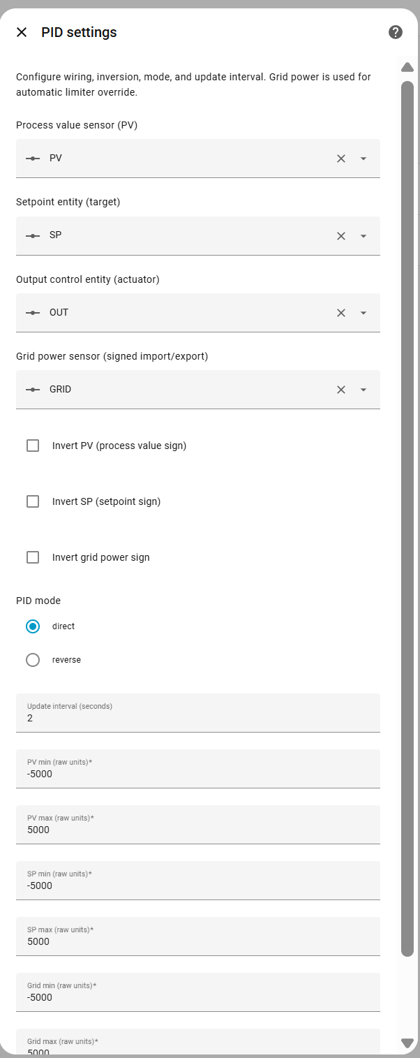
After installation, you can configure signal interpretation and controller behavior.
- Process Value Entity – Entity providing the measured process value
- Supported domains:
sensor,number,input_number
- Supported domains:
- Setpoint Entity – Entity providing the target setpoint
- Supported domains:
number,input_number
- Supported domains:
- Output Entity – Entity to be controlled by the PID
- Supported domains:
number,input_number
- Supported domains:
- Grid Power Entity – Entity providing grid power measurement
- Supported domains:
sensor,number,input_number
- Supported domains:
- Invert PV – Flips the sign of the process value if your meter reports the opposite direction (default: disabled)
- Invert SP – Flips the setpoint sign (default: disabled)
- Invert Grid Power – Flips grid power sign to match hardware conventions (default: disabled)
- PID mode
- Direct – Increasing error increases output (default)
- Reverse – Increasing error decreases output
- Update interval – Control loop execution interval in seconds (default: 10, minimum: 1)
- PV min/max – Scaling range for process value normalization in raw units (default: -5000.0 to 5000.0)
- SP min/max – Scaling range for setpoint normalization in raw units (default: -5000.0 to 5000.0)
- Grid min/max – Scaling range for grid power normalization in raw units (default: -5000.0 to 5000.0)
Runtime controls allow switching modes and manually overriding behavior.
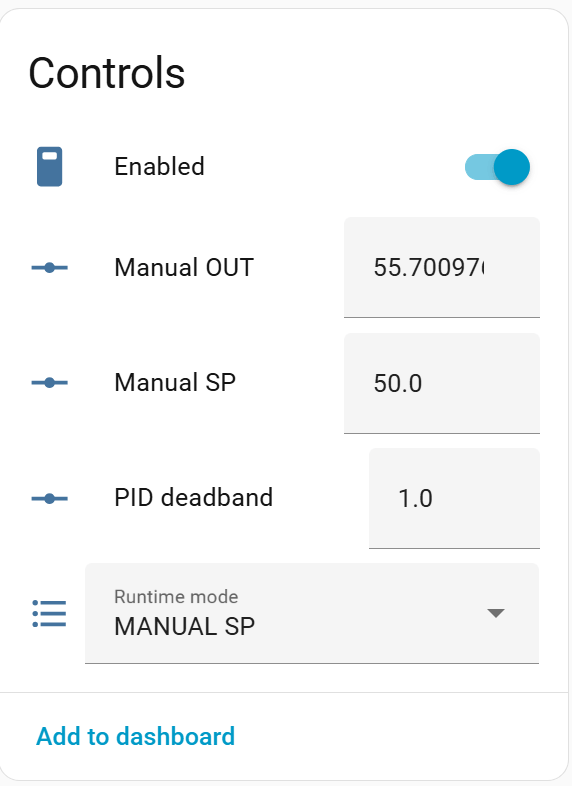
| Mode | Description |
|---|---|
| AUTO SP | PID controls output using normalized percent PV/SP (default) |
| MANUAL SP | User sets setpoint manually (raw units), PID remains active |
| MANUAL OUT | User directly controls output (raw units) |
| HOLD | Output frozen at last value |
Mode transitions use bumpless transfer to avoid output jumps.
- Enabled – Master enable/disable switch for the controller (default: enabled)
- Runtime mode – Current operating mode (AUTO SP, MANUAL SP, MANUAL OUT, HOLD)
- Manual SP value – Manual setpoint value in raw units (only active in MANUAL SP mode)
- Manual OUT value – Manual output value in raw units (only active in MANUAL OUT mode)
The integration exposes detailed runtime sensors for transparency and tuning.
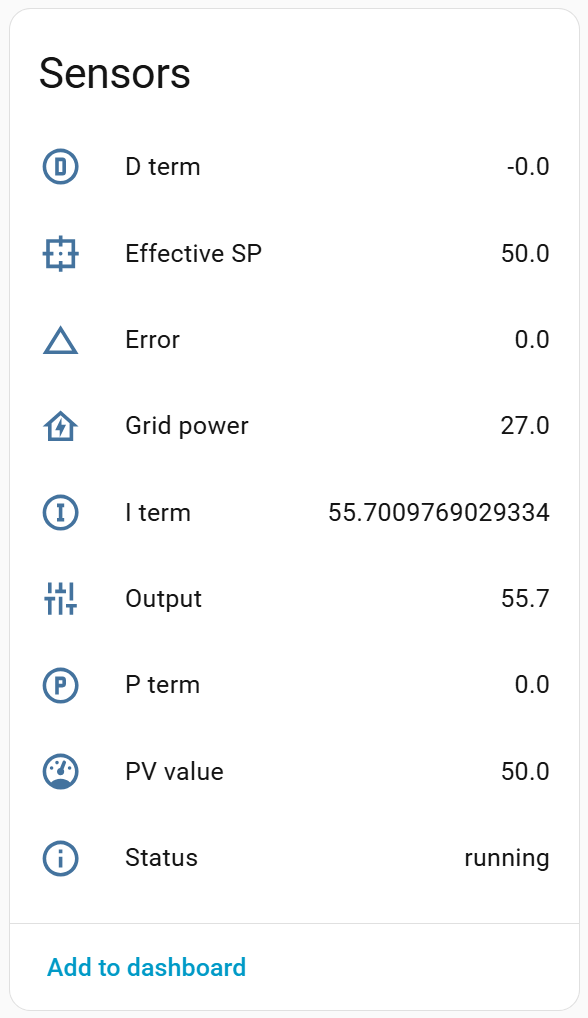
- Effective SP (raw units)
- PV value (raw units)
- Output (raw units)
- Output (pre rate limit)
- Error (percent domain)
- Grid power (raw units)
- P / I / D terms (percent domain)
- Limiter state (diagnostic)
- Status
Note: PV/SP/Output sensors show raw values. PID calculations are performed internally in percent.
All tuning and limiter parameters are available as number and switch entities.
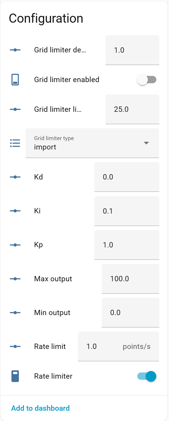
- Kp, Ki, Kd – PID gains (percent-based tuning)
- Kp: Proportional gain (default: 1.0)
- Ki: Integral gain (default: 0.1)
- Kd: Derivative gain (default: 0.0)
- PID deadband – Deadband in percent (default: 0.0)
- Output changes only when error exceeds this threshold
- Min output – Minimum output value in raw units (default: 0.0)
- Max output – Maximum output value in raw units (default: 11000.0)
- Grid limiter enabled – Enable/disable grid power limiting (default: disabled)
- Grid limiter type – Import or export limiting
- Import: Limits when importing from grid
- Export: Limits when exporting to grid
- Grid limiter limit – Limit threshold in raw units (default: 1000.0)
- Grid limiter deadband – Deadband in raw units (default: 50.0)
- Hysteresis to prevent oscillation around the limit
- Rate limiter enabled – Enable/disable output rate limiting (default: disabled)
- Rate limit – Maximum output change rate in raw units per second (default: 0.0)
- Prevents sudden output changes
- Max output step – Maximum allowed output step change (default: 0.0, disabled)
- Limits the maximum change per update cycle
- Output epsilon – Minimum output change threshold (default: 0.0, disabled)
- Output only changes if the difference exceeds this value
Additional diagnostic entities help understand controller behavior.
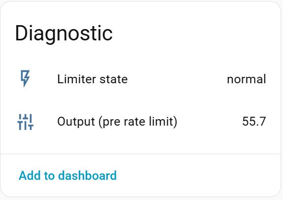
- Limiter state
- Output (pre rate limit)
The Status sensor may report:
runningdisabledholdmanual_outmissing_inputinvalid_outputgrid_power_unavailablelimiting_importlimiting_exportoutput_write_failed
These reflect internal controller state and error conditions.
The Solar Energy Controller integration uses a polling-based data update mechanism. The integration periodically reads the current state of the configured entities (Process Value, Setpoint, Grid Power, and Output) and recalculates the PID output.
- Polling-based: The integration actively polls Home Assistant entity states at regular intervals
- Default polling interval: 10 seconds
- Configurable: The update interval can be adjusted in the integration options (minimum: 1 second)
- Dynamic updates: Changes to the update interval are applied immediately without requiring a restart
-
At each update cycle, the coordinator:
- Reads the current state of the Process Value (PV) entity
- Reads the current state of the Setpoint (SP) entity
- Reads the current state of the Grid Power entity (if configured)
- Reads the current state of the Output entity
- Normalizes all values to 0–100% using the configured min/max ranges
- Calculates the PID output based on the error (SP - PV)
- Applies grid limiter and rate limiter constraints
- Writes the new output value to the Output entity
-
The update interval determines how frequently this cycle repeats
- Polling overhead: More frequent updates (lower interval) increase Home Assistant state reads and writes
- Entity availability: If any required entity becomes unavailable, the controller will log the issue and continue with the last known values where appropriate
- Not real-time: Due to polling, there is a delay between actual changes in sensor values and controller response (up to the update interval)
- Designed for slow systems: The integration is optimized for energy systems with seconds-level dynamics, not millisecond-level real-time control
- Energy systems (solar, grid, EV charging): 10–30 seconds (default: 10 seconds)
- Faster response needed: 5–10 seconds (increases system load)
- Very slow systems: 30–60 seconds (reduces system load)
The following automation examples demonstrate common use cases for the Solar Energy Controller integration.
Automatically adjust the setpoint based on available solar power:
automation:
  - alias: "Adjust PID Setpoint Based on Solar"
    trigger:
      - platform: numeric_state
        entity_id: sensor.solar_power
        above: 0
    condition:
      - condition: state
        entity_id: select.charger_pid_runtime_mode
        state: "AUTO SP"
    action:
      - service: number.set_value
        target:
          entity_id: number.charger_pid_setpoint
        data:
value: "{{ states('sensor.solar_power') | float }}"Disable the controller when solar production is zero (nighttime):
automation:
  - alias: "Disable PID Controller at Night"
    trigger:
      - platform: numeric_state
        entity_id: sensor.solar_power
        below: 100
    condition:
      - condition: state
        entity_id: switch.charger_pid_enabled
        state: "on"
    action:
      - service: switch.turn_off
        target:
entity_id: switch.charger_pid_enabledAutomatically enable the grid limiter during peak electricity hours:
automation:
  - alias: "Enable Grid Limiter During Peak Hours"
    trigger:
      - platform: time
        at: "14:00:00"  # Start of peak hours
    action:
      - service: switch.turn_on
        target:
          entity_id: switch.charger_pid_grid_limiter_enabled
      - service: number.set_value
        target:
          entity_id: number.charger_pid_grid_limiter_limit
        data:
          value: 1000  # Limit to 1000W import

  - alias: "Disable Grid Limiter After Peak Hours"
    trigger:
      - platform: time
        at: "22:00:00"  # End of peak hours
    action:
      - service: switch.turn_off
        target:
entity_id: switch.charger_pid_grid_limiter_enabledSwitch to manual output mode and set a low output value when battery is low:
automation:
  - alias: "Switch to Manual Mode When Battery Low"
    trigger:
      - platform: numeric_state
        entity_id: sensor.battery_soc
        below: 20
    condition:
      - condition: state
        entity_id: select.charger_pid_runtime_mode
        state: "AUTO SP"
    action:
      - service: select.select_option
        target:
          entity_id: select.charger_pid_runtime_mode
        data:
          option: "MANUAL OUT"
      - service: number.set_value
        target:
          entity_id: number.charger_pid_manual_out_value
        data:
value: 1000 # Set low output (1000W)Send a notification when the controller encounters an error:
automation:
  - alias: "Notify on PID Controller Error"
    trigger:
      - platform: state
        entity_id: sensor.charger_pid_status
        to:
          - "missing_input"
          - "invalid_output"
          - "output_write_failed"
    action:
      - service: notify.mobile_app
        data:
          title: "PID Controller Alert"
          message: "Controller status: {{ states('sensor.charger_pid_status') }}"
Note: Replace entity IDs (e.g.,
charger_pid_*) with your actual entity names. Entity names are based on the name you gave your controller instance during setup.
- Symptom: The configuration form shows errors like
entity_not_foundorentity_unavailablefor PV, SP, Output, or Grid entities. - Description: The selected entities either do not exist in Home Assistant or are currently
unavailable/unknown. - Resolution:
- Go to Settings → Devices & Services → Entities and verify that the selected entities exist and have valid states.
- Ensure the underlying integrations (e.g., inverter, charger, meter) are loaded and working.
- Refresh the entity list in the config flow (close and reopen the flow) and reselect the entities.
- If the entity is often
unavailable, fix the underlying integration before using it with the controller.
- Symptom: The
Statussensor reportsmissing_inputorgrid_power_unavailable, and the controller does not regulate as expected. - Description: One or more required inputs (PV, SP, Output, Grid) are missing or unavailable.
- Resolution:
- Check the Status sensor and the individual PV/SP/Output/Grid sensors to see which one is
unavailableorunknown. - Fix the upstream integration (e.g., restore communication with the inverter or meter).
- Verify the configured entities in Settings → Devices & Services → Solar Energy Controller → Configure.
- Once all inputs are available again, the controller will automatically resume normal operation.
- Check the Status sensor and the individual PV/SP/Output/Grid sensors to see which one is
- Symptom: The Output entity remains constant even when PV/SP change.
- Description: The controller may be disabled, in HOLD mode, or limited by rate/step constraints.
- Resolution:
- Check the Enabled switch entity and ensure it is turned on.
- Verify the Runtime mode select is set to
AUTO SP(or the desired mode, notHOLD). - Check Rate limiter and Max output step values; very small limits can effectively freeze the output.
- Confirm that the Output entity accepts the commanded values (no validation in the target integration blocks changes).
- Symptom: Changing
Manual SPorManual OUTresults in errors or values snapping back. - Description: Manual values can only be set when the controller is in the corresponding manual mode.
- Resolution:
- Set Runtime mode to
MANUAL SPbefore changing the Manual SP value, or toMANUAL OUTbefore changing the Manual OUT value. - If you see a service error like “Cannot set Manual SP value: controller is in AUTO SP mode”, switch to the correct mode and retry.
- Verify that no automation is continuously overwriting the same entities.
- Set Runtime mode to
- Symptom: Lovelace shows
Custom element not found: pid-controller-minior the mini card does not load. - Description: The frontend resources for the custom card are not registered or not served.
- Resolution:
- Ensure the integration is installed via HACS and Home Assistant has been restarted.
- If Lovelace is not in storage mode, manually add the resources:
- Go to Settings → Dashboards → Resources.
- Add the following URLs as JavaScript module resources:
/solar_energy_controller/frontend/pid-controller-mini.js/solar_energy_controller/frontend/pid-controller-popup.js
- Clear your browser cache and reload the dashboard.
The following are known limitations of the integration. These are design decisions and constraints, not bugs. For bug reports, please use the issue tracker.
- Output entity: Must be
numberorinput_number(cannot usesensorentities as output) - Setpoint entity: Must be
numberorinput_number(cannot usesensorentities as setpoint) - Process Value entity: Can be
sensor,number, orinput_number - Grid Power entity: Can be
sensor,number, orinput_number
- Polling-based updates: The integration uses polling, not push-based updates. Response time is limited by the update interval (minimum: 1 second)
- Not real-time: Designed for energy systems with seconds-level dynamics, not millisecond-level real-time control
- Update interval: Minimum polling interval is 1 second. Very fast updates (< 5 seconds) may increase system load
- Single output entity: Each controller instance can only control one output entity at a time
- No YAML configuration: Configuration must be done through the Home Assistant UI (config flow and options flow)
- No multiple instances with same entities: The integration prevents creating multiple controller instances with the same PV, SP, and Output entity combination (enforced by unique ID)
- No historical data storage: The integration does not store historical PID calculations or state changes. Use Home Assistant's history feature to track entity states
- No remote API: The integration only exposes Home Assistant entities. There is no separate API or remote control interface
- No backup/restore of PID state: PID internal state (integral term, previous values) is not persisted across restarts
- Entity availability: All configured entities (PV, SP, Output, Grid) must be available in Home Assistant. The controller will log warnings if entities become unavailable
- Home Assistant version: Requires Home Assistant 2023.9.0 or later