This project implements a digital voltmeter and ohmmeter based on an ESP32 microcontroller, featuring a graphical user interface displayed on a 128x64 SSD1306 OLED screen.
The device operates as a basic electronic measuring instrument, capable of switching between voltage and resistance measurement modes using a digital input.
The system provides:
- 🔌 DC voltage measurement using a resistive voltage divider
- 🧮 Resistance measurement using a software-controlled auto‑ranging method
- 📟 Real‑time visualization with animations on an OLED display
The firmware is written using the Arduino framework, and most of the system behavior is defined directly in the main .ino file.
A complete electrical schematic is not included in this repository. The project was developed as an experimental and educational prototype, and the hardware connections are defined implicitly by the firmware.
However, the hardware can be described at a functional level, based strictly on the code:
-
ESP32 development board
-
OLED Display: 128x64 SSD1306 (I2C)
-
Reference resistors for ohmmeter auto‑ranging:
- 1 kΩ
- 10 kΩ
- 100 kΩ
-
Voltage divider for DC voltage measurement
-
Mode selection input (digital)
-
Status LED
| Function | Description |
|---|---|
OhmMeter |
Analog input used for resistance measurement |
voltMeter |
Analog input used for voltage measurement |
R1, R2, R3 |
Digital pins controlling reference resistors |
modeInput |
Digital input for mode selection (Voltmeter / Ohmmeter) |
LED |
Digital output for status indication |
⚠️ Note: Pin numbers and electrical topology must be inferred from the firmware. No assumptions beyond what is explicitly implemented in the code are made.
- The ESP32 ADC samples the voltage through a resistive divider.
- Multiple ADC readings are averaged to reduce noise.
- The measured ADC value is scaled using a calibration factor defined in the firmware.
- The system uses three reference resistors to implement auto‑ranging.
- A finite state machine sequentially enables each resistor.
- ADC readings are averaged and converted into resistance values.
- The most suitable range is automatically selected in software.
- Over‑range and under‑range conditions are detected and displayed.
- 🔁 Dual measurement modes: Voltmeter and Ohmmeter
- 🧠 Software‑based auto‑ranging resistance measurement
- 📊 ADC averaging for stable readings
⚠️ Over Load / Under Load detection- 🎞️ Animated OLED graphical interface
- 💡 LED status indicator
Click the image below to watch the full demonstration video on YouTube:
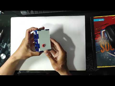
Below are two photographs of the physical prototype:


-
Microcontroller: ESP32
-
Programming Language: C / C++
-
Framework: Arduino
-
Display: SSD1306 OLED (128x64)
-
Libraries:
- Adafruit_SSD1306
- Adafruit_GFX
- Arduino IDE
- ESP32 board support installed
- USB cable
- Clone this repository:
git clone https://github.com/your-username/your-repository-name.git- Open the
.inofile in Arduino IDE. - Install required libraries using the Arduino Library Manager.
- Select the appropriate ESP32 board and COM port.
- Upload the sketch to the board.
- Practical use of the ESP32 ADC
- Noise reduction through sampling and averaging
- Implementation of a software‑based auto‑ranging ohmmeter
- State machine design for measurement sequencing
- Embedded graphical interface development
- Add a complete electrical schematic
- Improve ADC calibration accuracy
- Add current measurement mode
- Implement serial data logging
This project is released under the MIT License.
Developed by: